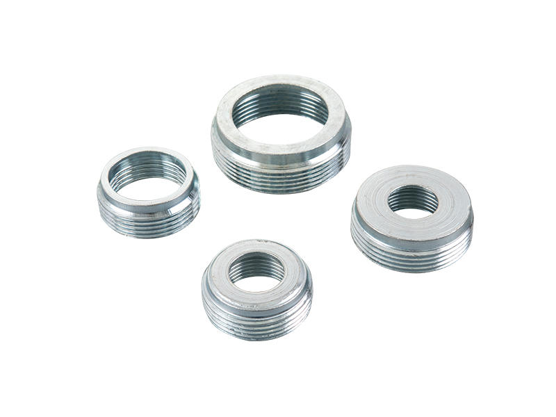
Zinc die casting offers exceptional precision, smooth surfaces, and high strength-to-weight ratios for fittings across automotive, electronics, and hardware. Yet, flawed design practices drastically increase defects like porosity, cracks, or distortion—jeopardizing performance and escalating costs. By sidestepping these common errors, engineers ensure manufacturable, reliable, and cost-efficient components.
1. Ignoring Wall Thickness Uniformity & Limits
Error: Designing walls too thick (>6mm), excessively thin (<2.5mm), or with abrupt transitions.
Why it fails: Thick sections solidify slower, forming internal shrinkage cavities or porosity. Thin walls hinder metal flow, causing cold shuts (incomplete fills) or fragility. Non-uniform walls create uneven cooling stresses, warping the part.
Solution: Maintain uniform walls at 2.5–4 mm, with transitions tapered gradually. Use ribs for structural support instead of thickening sections.
2. Poor Gating System Design
Error: Undersized or misaligned gates, incorrect runner geometry, or high-velocity impingement on cores/cavities.
Why it fails: Turbulence from undersized gates traps gases, causing porosity. Metal jetting against surfaces erodes dies or creates cold flakes. Inadequate runners slow fill rates, risking misruns.
Solution:
Position gates to avoid direct cavity冲击 (use angled or multiple gates).
Design runners with tapered cross-sections (exit 10–30% smaller than entry) to reduce gas entrapment.
Ensure gate thickness supports laminar flow.
3. Overlooking Radii & Draft Angles
Error: Sharp corners (0° radii) or insufficient draft angles (<1–3°).
Why it fails: Sharp corners concentrate stresses during cooling/ejection, initiating cracks. Inadequate draft angles cause drag marks, sticking, or ejection deformation.
Solution:
Apply minimum radii of R2 mm to all internal/external corners.
Incorporate draft angles of 1–3° (higher for deeper features). Polished surfaces may need steeper drafts.
4. Underestimating Material Purity & Harmful Impurities
Error: Specifying alloys with uncontrolled levels of lead (Pb), cadmium (Cd), or tin (Sn).
Why it fails: These impurities migrate to grain boundaries, causing intergranular corrosion. Over time, fittings swell, crack, or fail catastrophically—especially after plating or in humid environments.
Solution: Use alloys meeting ASTM B86 or GB/T 13821 standards (e.g., Zamak 3/5). Enforce strict traceability for raw material purity.
5. Inadequate Venting & Overflow Planning
Error: Insufficient vents, blocked exhaust channels, or undersized/absent overflow wells.
Why it fails: Trapped air and gases form blowholes, blisters, or incomplete fills. Without overflows, cold fronts (oxide layers) enter the cavity, causing weak seams.
Solution:
Add vents (0.12–0.15 mm deep) near end-of-fill zones.
Place overflow wells at flow junctions to capture contaminants.
Ensure combined vent/overflow area is 20–30% of gate area.
6. Neglecting Ejection System Coordination
Error: Poorly positioned/stunted ejector pins, or neglecting post-ejector stresses.
Why it fails: Uneven force bends thin walls during ejection. Short pins scar surfaces; long pins dent fittings. Residual stresses from premature ejection cause delayed distortion.
Solution:
Distribute pins uniformly near high-friction zones (cores/deep ribs).
Set ejection delays ≥0.5 seconds for partial solidification.
Polish pins/cores to Ra ≤0.4 μm to minimize adhesion.
Key Takeaway
Zinc die casting combines efficiency and precision—if designs respect process boundaries. Avoiding these six errors prevents up to 90% of defects like porosity, cracks, or dimensional instability. Partner with foundries early in design reviews to optimize gating, venting, and tolerances. Rigorous adherence to geometric rules (wall thickness, radii, draft) and material standards transforms theoretical robustness into flawless, lasting fittings.


 English
 中文简体
中文简体


 Request A Quote


